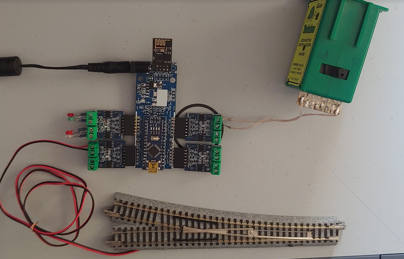
Ever want to control a snapping or momentary-coil-action turnout or device, like Kato, Atlas and others make. But, we only have 2 pins (already used for i2c), and you have 8 turnouts??? So why not put an inexpensive Arduino Nano in the way? And use it to control 4 x L9110S dual h-bridge control boards?
As it turns out, when you set the time to be ON in milliseconds to zero, it will STAY on and thus drive ANY stallmotor turnout too! So TortoiseTM, here we are…
We called it the “mqTrains Turnout Nano” and have it labelled as mqTrains_TurnoutNano_only. Very easily found with a search at OSHWLab: https://oshwlab.com/search?wd=mqtrains
The code for the Nano and ESP will appear on github shortly…
TortoiseTM is most likely trademarked by Circuitron Inc.
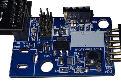
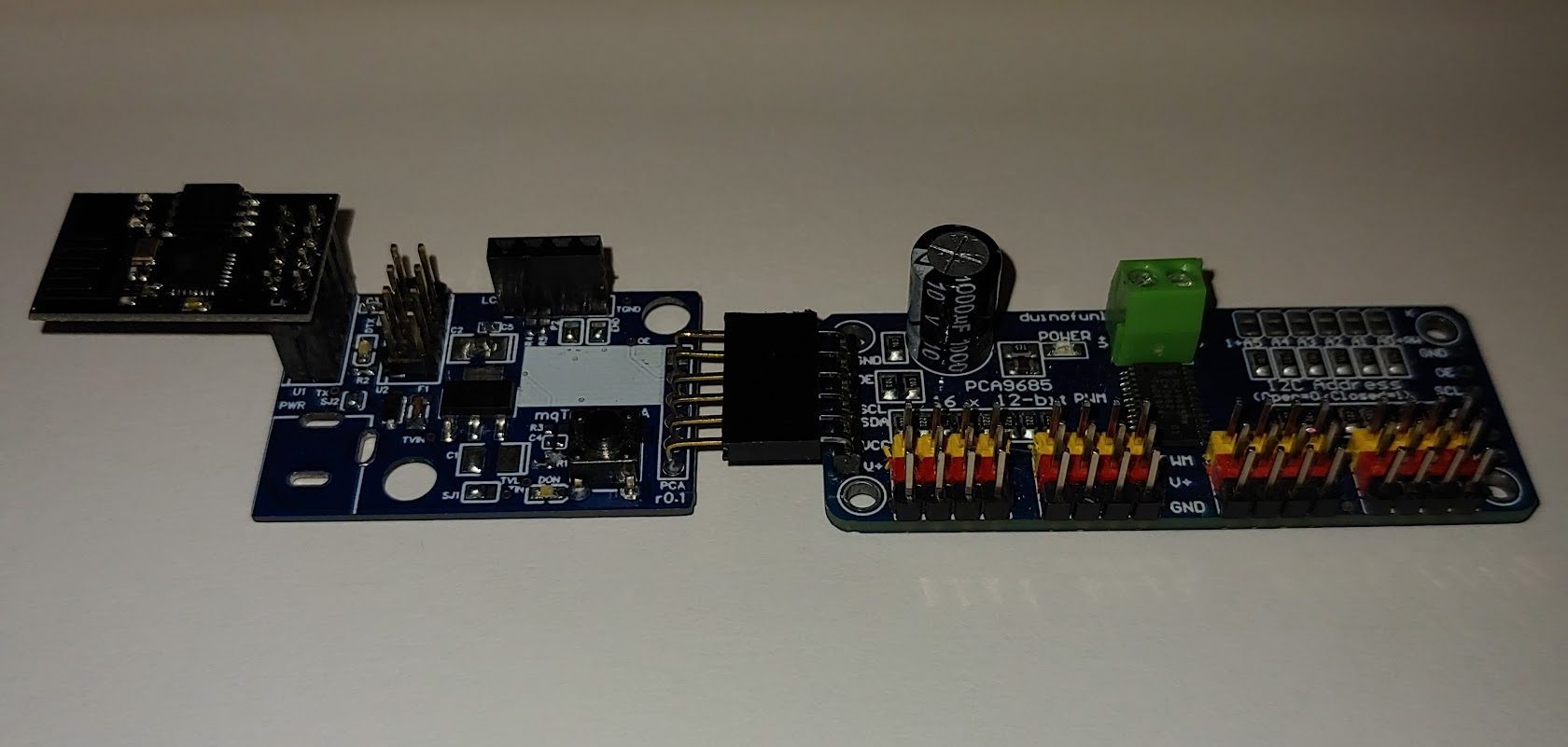
Waau, it took the start of a whole new year to get the ESP01’s interface board to the PCA9685 shared with the world! We called it the “mqTrains PCA9685 Servo Turnout Controller” and have it labelled as mqTrains_PCA_02. Very easily found with a search at oshwlab: https://oshwlab.com/search?wd=mqtrains
So, first warning, don’t just buy all the parts as listed in the BOM, they were the closest and easiest parts to use in the EasyEDA library, read the schematic and find the best 10 uF capacitor in a 3.5 x 2.8 package, or just a trusted 1206 part.
Second, using the EasyEDA tools, you can order the PCBs themselves from JLCPCB for $4 for 5 boards, not per board, all 5 together…or $5 for 10 boards, or $14.80 for 100 boards. BUT, here is the second warning, you will only know the “shipping” part when you place the order and enter your shipping address. Which requires a few more choices: Make us proud and order them in blue, and to save some shipping in weight, reduce the board thickness to 1 mm, but be careful changing other settings, since 0.4 mm thick boards will require ENIG-RoHS (read “Electroless nickel immersion gold“) and GOLD cost more. The problem is, when you change it back to 1 mm, it is still set to ENIG-RoHS, it does not switch back to the cheaper HASL or LeadFree HASL.
Also spend the extra $1.50 and remove the “Order Number” from the board, since I don’t think you want some random number printed all across it. So, to repeat: best things to choose: Number of boards, more will cost more, but less per board, so 5 boards might be $0.40 or $0.80 a piece (take the first time offer) or $0.07 per, when ordering 500; Reduce the board thickness: 1 mm or thicker gives options to pay more for shorter production times, but 1 mm saves money on shipping; Pick Blue as PCB Color (you never want to solder darker color boards: it is really hard to find the 0402 resistor you just placed on it! Blue is also free, compared to purple, red or yellow); And then decide to deal with lead or tin whiskers by selecting HASL or HASL-RoHS.
You can ALSO just generate the Gerber files and order the PCBs from anywhere else you like. A quick Google search will bring you to several places to deliver PCBs to your front door.
The only parts required, are the LM1117-3.3V; at least the two 10 uF capacitors and the 0.1 uF at C3, the LEDs and 1 kOhms are encouraged and a female single row for the PCA connector and a double row for the ESP01 at U1. The diode D1 can be short circuited if you use the 5V from the PCA side (short SJ2) and the re-settable fuse (F1) is only needed on your first 5 boards, after that you know what not to short to what and the fuse serves less of its safety and accident protection purpose! When you buy the OLED LCD you need to check if the GND pin is on the end or not, since they make them in 2 kinds, and then solder the jumpers at END and P2 appropriately. If you get the kind with the GND pin at the end, then follow the jumper suggestion in the schematic. I soldered a male to male 4 pin connector to my LCD, so I can temporarily hold the LCD in place when the ESP boots up, read the IP address and MQTT messages when they show up and then pull the LCD out, it has served its purpose…so only your first few boards might need a 4 pin female connector, the rest can just have the LCD temporarily held in place in the holes. Just know, the LCD needs to be initialized and that only happens on power up or with a reboot. So plugging it in later will not make it work. You have to press RESET when live, or power the system up. Which brings us to the button (RST) and resistor R3 and capacitor C4…I would guess none are required, unless the ESP somehow does not have RST pulled up, then ONLY R3 would be needed.
If you don’t have a PCA9685 connected, then you won’t have i2c pull-up resistors, and if the LCD does not have them, then R4 and R5 might be needed. U2 is there to install a male 2×4 header, so you could wire the ESP01 to a breadboard for other projects. But now the PWR connector, more money, is needed again. A PCA9685 might be less expensive than a 2.5 mm barrel connector, just saying!
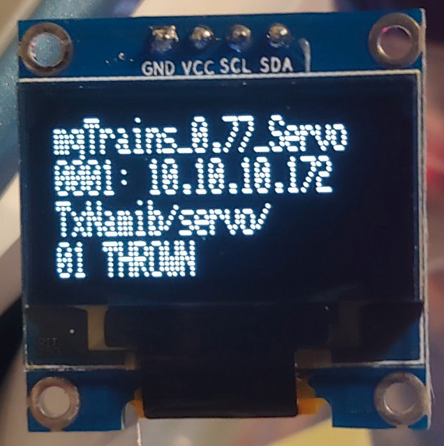
When you power up an mqTrains module, on first power up, it will create an access point (AP) mqTrains-0001 and you can use your computer, phone or tablet to connect to it…you then proceed to 2.2.2.1 with your browser to get to the web page to configure it, and when you are successful in configuring your SSID, WepKey, MQTT’s IP Address and the base topic to subscribe too, it will reboot, connect to your WiFi router, connect to the MQTT broker (server) and publish the IP address of the module to with "/baseTopic/IPA 10.10.10.172 is here!", and now you know where to find the web page again to configure the servos and I/O as you need. The AP will turn off once the module publish the IPA message. Next power cycle AP on again and off when IPA is published. So you have a way to reconnect to it on power up. But, if you don’t have a way to see the MQTT messages easily, we just added and tested a very inexpensive SSD1306 OLED LCD module (also explained in a Random Nerd Tutorial here). So consider having one or two LCDs handy to monitor your first mqTrains device:
Okay, we are getting closer to the release, so you might want to start getting some parts and install some software! We might just release the binary files first, in which case you would need to read up on PlatformIO, or if we just want you to get lost in all the details, we will upload all the code into github or gitlab to use with the Arduino IDE.
So, starting with the latter, the Arduino IDE (we recommend at least version 1.8.12) is needed with the tool set to compile and upload the code (ESP8266 Community version 2.7.4 recommended), as well as the little tool to upload the file system (at least version 2.6.0) with the web pages and .json configuration files (how to here).
And then you are going to need all the libraries installed required to make this work. You should be able to download and install most of them within the Arduino IDE, just make sure that the ESPAsyncWebServer is also installed, even though it might come from another package when you do the search in Manage Libraries… (Ctrl+Shift+I). If not, just as easy to download and unzip the code from here: https://github.com/me-no-dev/ESPAsyncWebServer.
cd libraries && git clone https://github.com/me-no-dev/ESPAsyncWebServer.git
ESPAsyncTCP at version 1.2.2 https://github.com/me-no-dev/ESPAsyncTCP
cd libraries && git clone https://github.com/me-no-dev/ESPAsyncTCP.git *
mDNS:
esp8266_mdns at version 1.1.7
Hash at version 1.0
Ok, now that you have all the software tools under control, here is the minimum Hardware needed:
Computer to run all the software above on, and that includes operating systems like Windows, Linux and Mac, even Raspbian.
A USB connector for a USB cable to go to the ESP8266 programmer
An ESP8266 programmer board that makes USB into RX/TX, provides 3v3 to the ESP and has a switch or button to pull the GPIO low on ESP power up, to put it in boot mode.
And ESP8266, and this can be any NodeMCU variant, but in order to make this as inexpensive as possible, and limit the growth in software, an ESP-01 is sufficient to connect to the i2c modules or the 1-wire LEDs for the first round
A PCA9685 PWM driver module, with a 5V power supply capable of enough Amps to control all you 16 servos from anywhere to anywhere else, even at startup, when they all will consume power!
Or a MCP23017 module with the 16 I/O pins to read sensors or control ouputs (3.3V at this point)
Or a whole bunch of WS2811 or WS2812b devices to control LEDs on one looooong wire.
We are in the process of making the interface hardware between the Modules and ESP01, but if you can solder 4 wires (3v3, GND, SCL and SDA) on top of the ESP01 (or to the NodeMCU) you are ready.
Starting mosquitto from the command line, you can use the ‘-v’ (or ‘–verbose’) option for showing verbose messages…this will override the logtype option in the config file. So first step, when something is not going right, start the MQTT server manually with mosquitto -v and watch what the server does while you debug the problem.
If you don’t have direct access to the Broker/Server, you can also check out MQTTBox http://workswithweb.com/mqttbox.html, works on most platforms…great tip from David B., thank you.
Create a new MQTT Client, with some unique MQTT Client Name (MeBox will work), select the protocol you are using in your application, and enter the hostname or IP address for the Host. Enter Username and Password, if used, and check or uncheck all the other boxes that are application to your setup. Then click Save and selecting the “MeBox” client in the list, will allow you to add Publishers to Publish to a Topic, or Subscribers to Subscribe to one or more Topics, with the wildcards (Single Level ‘+’ and Multilevel ‘#’) , as usual.
Very easy to monitor and interact with the MQTT Server: a Published message has a “Publish again” arrow, avoiding quite a but of typing.; restarting MQTTBox will automatically connect (if the option was selected), but you will need to click the Subscribe button in each Subscriber window.
esptool.py v2.8
Serial port COM4
Connecting......_
Enable verbose output with Settings (Ctrl+Comma). File -> Preferences -> Show verbose output during: [ x ] compilation [ x ] upload
So, if we do this in Linux or on a Mac or Raspberry Pi: All we need is sudo apt-get update sudo apt-get install python python-pip sudo pip install esptool
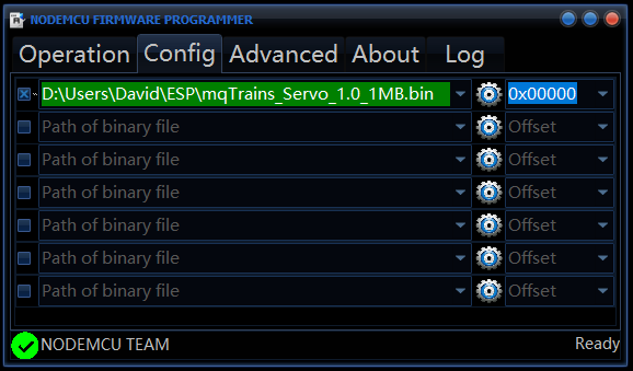
For the Windows kind, there is a Nodemcu-Flasher tool here in a 32 and 64 bit version which you can specify the bin file on the Config tab:
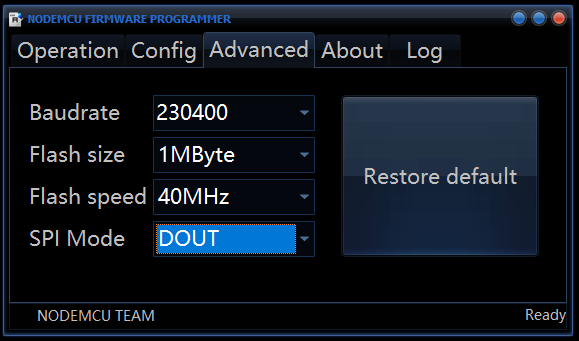
Set the appropriate Flash Size, Flash speed and SPI Mode on the Advanced tab:
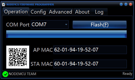
And then head back to the Operation tab and a click “Flash(F)”:
Of course, the Windows device driver needs to be in place for the USB programmer you are using (COM7 shown here).
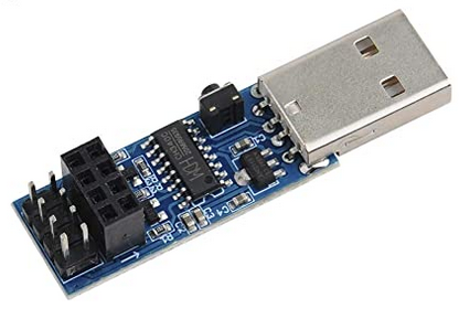
We also recommend using this little DYI Mall programmer which avoids the slide switch at power up to be in program mode, but instead gives you a reset button and the same 8 pins on the ESP-01 to connect to the next i2c board:
To start the service, Computer Management (right-click on My Computer, Manage) -> Services and Applications->Services->Mosquitto Broker->right click->Start
(You can also set the service to Automatic in right click on the service->Properties->Startup type)
If not run as a service, you can start it with C:\”Program Files”\mosquitto\mosquitto.exe -v -c “C:\Program Files\mosquitto\mosquitto.conf”
To test, run: C:\Program Files\mosquitto\mosquitto_sub -h localhost -v -t “TxNamib/#”
If the service is not running or accessible, the error wil show: Error: No connection could be made because the target machine actively refused it.
Else, you will only see a message if it was “retained”, or you publish something to TxNamib now C:\”Program Files”\mosquitto\mosquitto_pub -h localhost -t “TxNamib/servo.2003/03” -r -m “CLOSED” or C:\”Program Files”\mosquitto\mosquitto_pub -h localhost -t “TxNamib/servo.2003/03” -r -m “THROWN”
Ubuntu and Raspberry Pi (3, 4, 400 and Zero W): sudo apt-get install mosquitto
or
snap install mosquitto
Older versions of Ubuntu: sudo apt-add-repository ppa:mosquitto-dev/mosquitto-ppa sudo apt-get update